WEBSITE UPDATE:

Due to the increased difficulty in people accessing this website and the sister, due to certificate issues from YolaI am slowly migrating to Wordpress during 2023.  These camera repair pages will remain here, but will no longer be updated.

For recent cine resource updates, please visit: https://aussiecine.wordpress.com/

For recent camera listings, please visit: https://aussiecinerepair.wordpress.com/

PENTAFLEX 16 Links can be found on the main Mishkin Productions site, HERE

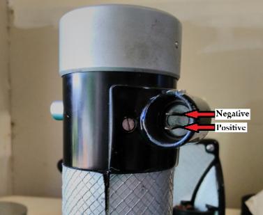
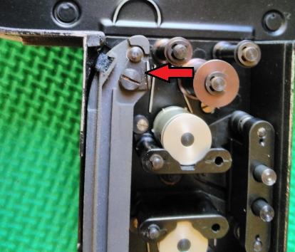
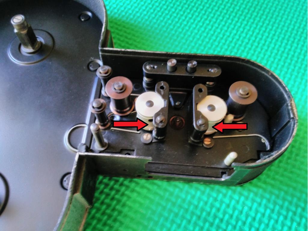
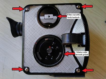
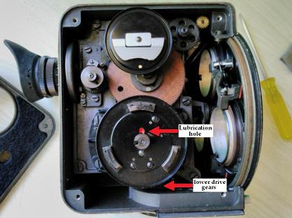
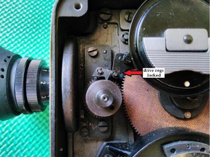
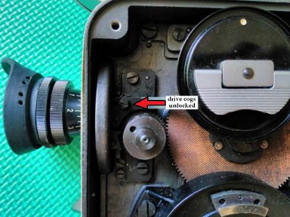
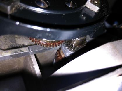
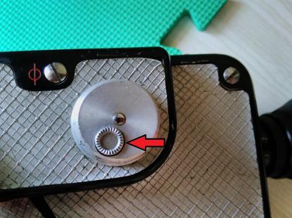
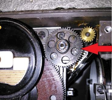
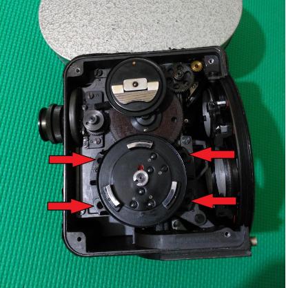
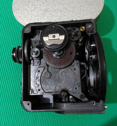
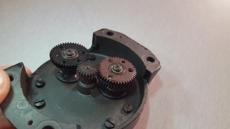
Dismantle:  The Pentaflex 16 left side cover can be removed by removing four screws visible on the casing.  Once the cover is removed, most of the cogs can be examined.  To manually move the cogs by hand, a film cassette has to be inserted into the body, or simply rotate and engage the cassette lock.  To test if the motor runs, attach to a 12 volt motorcycle battery.  

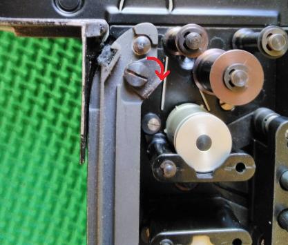
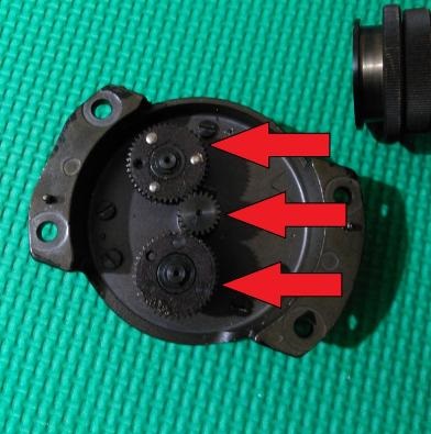
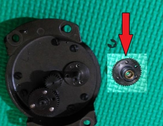
Lubrication:  This particular camera, while running, had trouble maintaining a regular speed, fluctuating regardless of the motor speed setting.  After opening the casing, and lubricating with “Singer machine” oil, a very light viscosity oil suited for low load and speed applications, the camera was able to maintain what appeared to be very constant speed.

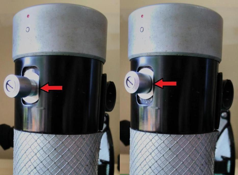
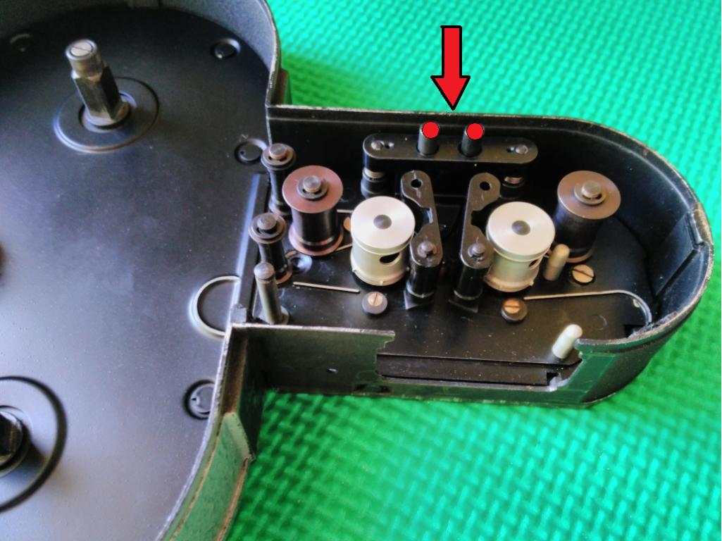
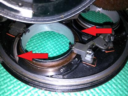
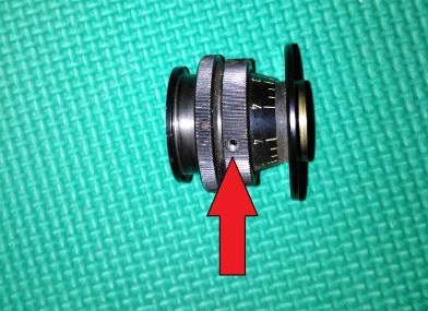
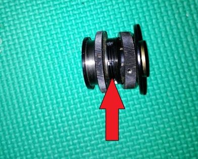
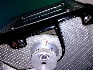
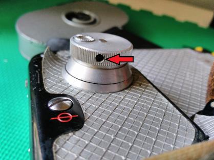
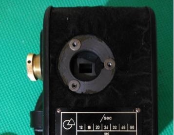
Dry Run Camera: Inserting a loaded film cassette, gently push the cassette into the top of the camera body, through the two "trap doors" on top of the casing.  Once the cassette is firmly seated, rotate the winder clockwise until the white dot is at the top, as per below picture, and the cassette moves forward slightly and audibly clicks into place.  To remove, simply rotate the winder anti-clockwise until the white dot is at the bottom, as per below picture, and the cassette moves backwards slightly.  Pull the cassette out of the camera body.

Note: It is worth noting that this camera has two names.  The original VEB factory designated the camera Pentacon AK16.  Later, under the DDR, the camera's name was changed to Pentaflex 16.  Parts between the two models are interchangeable, and essentially the only differences appear to be cosmetic.  Pentacon AK16's are black, Pentaflex 16's are silver coloured.


Manuals

Pentovar lens user manual.output.pdf Pentovar lens user manual.output.pdf
Size : 168.102 Kb
Type : pdf
Pentaflex 16mm technical data.output.pdf Pentaflex 16mm technical data.output.pdf
Size : 314.648 Kb
Type : pdf
                        CAMERA MOTOR/TRIGGER
Although the Pentaflex 16 was sold with a specific cable to connect the motor with a battery pack, if this is not available a substitute can be easily fashioned with widely available automotive crimp connectors.


Once the motor is locked into the camera body, this button, once pushed in, will run the camera.  To lock the camera in the "run continually" position, push in and slide up.  To release, slide the button down and release.


To ensure correct connection to a power source, ensure that the same wire connecting to "positive" on a battery, is the same wire connected to the positive indicated here.


FILM CASSETTE/MAGAZINE
The Pentaflex 16 was produced for use with three types of film cassette, 30, 60, and 122 meter.  Or 100, 200, or 400ft.  Most commonly available is the 100ft cassette.  The 100ft may be best considering some labs may only accept 100ft loads for processing.  Obviously larger labs will take 200 and 400ft loads. 


To remove the film guide and pressure plate, rotate the small tab to unlock the film guide.  Gently lift the guide upwards to remove.


Installation is the reversal of removal, be sure the film guide is sitting flat, do not force installation.


To open the arms for ease of loading film, simply push with your finger the two "arms" and they will click into the "open" position.


Once film is loaded, to move the two "arms" back into position, push down on both these buttons, and the "arms" will lock back into place.


The film guide contains a film pressure plate, two springs and a screw.  They are not stainless steel and are susceptible to rust.  In this picture, the pressure plate poles are rusted and will prevent the plate moving up and down smoothly, failing to firmly hold the film against the camera film gate. Removing the rust is difficult as the metal is fairly weak and the poles will break off.  Replace the guide with a better condition one or fabricate a repair.


To advance the film cassette rollers manually, for instance to ensure smooth threading of the film, use a small screwdriver or pen to push the indicated button in.  
The button is spring loaded, so releasing the pressure, locks the film cassette.  This button is automatically pushed in when the cassette is inserted into the camera body.


CAMERA BODY DISASSEMBLY & LUBE
There are four screws that hold the side casing in place.  When replacing, ensure the casing sits securely, with no possible light leakage


The two arrows indicated areas where lubrication can be applied.  As stated earlier, lubricate sparingly with correct lubricant.


When the film cassette is not inserted, the interior cog mechanisms cannot be moved.  


When the film cassette is inserted, the cog lock disengages, enabling manual movement of interior cog mechanisms.  Turning the film cassette handle clockwise without the cassette inserted, will also disengage the drive cogs.


Worm gears and cogs under the side motor mount, at the base of the camera.  Lubricating where the motor directly interfaces with the camera mechanisms is the best place to lubricate.  Excessive lubrication can be detrimental.


If the "synchromesh" lens diaphragm gearing is stiff, placing one drop of light viscosity oil in the gear grooves will help.


if the eyepiece is difficult to adjust, it will need lubrication.  Removing the small grub screw, as indicated, will enable the locking ring to be undone.


Once the locking ring is undone, place a few drops of oil into the cavity.  The grub screw has to line up with the holes of the thread in the cavity.  


SHUTTER ANGLE ADJUSTMENT

The shutter dial or physical opening timings of the shutter will need to be adjusted if cog teeth have broken off or the shutter dial rotates freely.


If the shutter dial has "free play" or slack, possibly the grub screw has become loose causing the dial to not correspond to the correct shutter position.  By turning the shutter to the fully closed position, then tightening the grub screw indicated, then the dial can be adjusted to be correct.  Start the adjustment on either 0 degrees or 180 degrees.


Loosening the grub screw enables you to position the dial correctly corresponding to the correct shutter position.


The small dial exerts tension on the shutter angle dial, making it easier or harder to turn the dial.


This cog drives the shutter. To adjust the time the shutter exposes the film gate, remove the small circlip, and lift the cog just enough to advance or retard the gold cog.


Like many cameras, light from the eyepiece can get onto the film.  For this the eyepiece shutter is open when the film gate shutter is closed, and closed when the gate shutter has exposed the film gate.  If the shutter needs to be adjusted manually, the above eyepiece shutter is at the correct position corresponding to the position of the gate shutter.


The above position of the shutter corresponds to the eyepiece shutter.  If both shutters are not synced, then stray light can get onto the film.


SHUTTER OPENINGS CORRESPONDING TO SHUTTER DIAL SETTINGS

In the event of having to manually correct the camera's shutter dial and shutter, using the below pictures may assist in "calibrating" the correct openings.
0 Degree shutter opening


30 Degree shutter opening


60 Degree shutter opening


120 Degree shutter opening


150 Degree shutter opening


180 Degree shutter opening


The following YouTube video details the mechanisms of the variable shutter on the Pentacon AK16/Pentaflex 16.  The original link is:https://www.youtube.com/watch?v=Ev-VChXpoZs


DRIVE COGS JAMMED OR NOT ENGAGING

With either the film cassette or cassette locking dial engaged, and the camera refuses to run, then a drive cog could be jammed or broken.  Or, the camera motor activates one of the drive mounts, but not the other one, then a cog could be damaged or broken.


Remove these 4 screws.  gently lift of the side motor mount.  On the underside of the mount are small steel guides, so when removing do not prise off or wiggle.  Attempt to raise the mount slowly if difficult to remove.


The side motor mount has been removed.  The main drive cog can be examined.  Be aware it is made of Bakelite material and can damage easily if care is not taken.  Examine the the cog for missing teeth. 


On the underside of the side motor mount you can see the Bakelite cogs that engage to drive the larger Bakelite cog on the camera bosy.  The bottom cog connects to the camera base motor mount.  The middle small cog connects to the motor when mounted to the side mount.  The top cog connects to the large drive cog. Remove the small circlip to slide  the cog off it's mount.


The cog that connected to the camera base motor mount was partially rounded off or missing several teeth.  This caused the camera drive motor to only run the camera via the side mount.  These cogs are Bakelite material, and as such easily damaged if a person attempts to force the camera to run without a motor, and the drive lock still engaged.  If the bottom cog loses teeth, when the motor is mounted to the base mount the motor will not be able to run the camera.  If the motor is attached to the side mount, it will still be able to run the camera.  If the top cog loses teeth, neither the side or base mounted motor will run the camera.        


REPLACING DRIVE COGS WITH DAMAGED TEETH
If one of the small drive cogs is damaged, you can engage the services of a person with a 3D printer to make some new cogs.  The modern 3D printer is a very useful machine for replacing impossible to replace parts.  In this instance, this Pentaflex camera was unusable, once the damaged cog was replaced, the camera now runs fine.  I used the services of Nathan from Queensland based Envision Engineering.  The company now have the cog dimensions on file and can print off spares if needed.  


Of the three cogs in this picture, two are the original Bakelite material, and one has been built with a 3D printer.  The 3D printed cog is a harder material than Bakelite and should last the life of the camera.  The dimensions are exactly the same as the original.  


The cogs are held onto their spindle with pins and a touch of solder on top.  The solder is rounded.  Attempting to drill into the rounded cap of the pin will be difficult, and the drill bit may slide and cut your finger.  I used a dremel power tool  with a grinder wheel to grind down the rounded cap and make it easier to drill a hole in the middle.  Do not use a vice to hold the spindle, you may bend the spindle out of shape or damage it.  


Looking at the about diagram, it shows the basic design of the pin.  Once the rounded cap is drilled a little, the cog should lift off.  There is no need to drill the pin out entirely.  Once you start drilling, use a 3.5mm size bit to start, this should remove most of the pin's cap.  Then use the 3mm and 2.5mm sized drill bits to drill just below the surface of the cog.  Not deep.  The pin stumps will be useful later.  


This shows a good result, the tops of the pins have been drilled off, and using a smaller drill bit, the pin has been drilled a little bit beyond the cog surface.  


Once the pin caps have been drilled out, you can use a small screw driver to gently pry the damaged top cog off.  The cog under it is metal and will not get damaged.     


This picture shows the cog has been removed, and you can see the remainders of the pins.  These pins are important to retain, as they hold the position of the spring attached to the bottom cog.  Removing the pins loosens the spring and the cog will simply slide, not remain still.  The spring is there to prevent the Bakelite cog getting jolted suddenly when the camera motor starts.      


Once the original damaged cog is removed, place the new cog into position.  Once the cog is seated well, no gaps, use hot glue or something similar to hold the cog in place and prevent it falling off.  


This picture is an example of where the cogs are situated after re-assembly and their relation to the large drive cog.  The picture displays clearly that if the bottom cog is damaged, the top cog will still run the camera.  However, if the top cog, here coloured black, is damaged, then the motor will not run the camera at all.     


The finished repair, ready to install.   


DISCLAIMER:
This is a Copyright Disclaimer under section 107 of the Copyright Act of 1976, allowance is made for “fair use” for purposes such as criticism, comment, news reporting, teaching, scholarship, education and research. Fair use is a use permitted by copyright statute that might otherwise be infringing.

Fair Use permits limited use of copyrighted material without having to first acquire permission from the copyright holder. Fair use is one of the limitations to copyright intended to balance the interests of copyright holders with the public interest in the wider distribution and use of creative works by allowing as a defense to copyright infringement claims certain limited uses that might otherwise be considered infringement.

The creator of this website declares that information and photographs copied from other websites and placed here is solely for the purpose of education and research.  The creator of this website does not earn money from information published here.  The creator of this website always references, where possible, the original creator of work that is published here.

If any person wants to dispute this, and/or believes the creator of this website has infringed on a person's copyrighted creative material, please email me at mishkin.film@gmail.com
This email address is checked frequently.