Prior to beginning disassembly of the camera body, follow all instructions described in "Hand grip replacement".
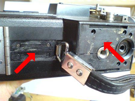
Remove all four screws as indicated by the left arrow. Then remove the four remaining screws indicated by the right arrow.
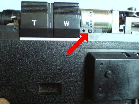
Remove this screw. If the hand grip has been removed, and the side cover as described earlier, you should be able to lift off this side of the camera body.
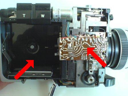
Once the cover has been removed you will see the cartridge compartment, and a circuitry board. If there is a severed solder, or burn out on the circuitry board, a repair can be made by an experienced person.
The left arrow indicates the film gate. Modification or repair of this should only be carried out by an experienced person. The right arrow indicates the ASA setting pins, these are depressed differently by the specific ASA requirements of the cartridge inserted.
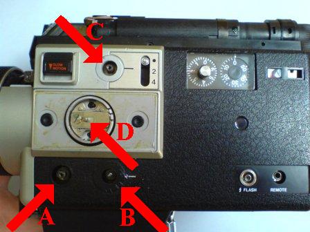
Each of the labelled dials need to be removed prior to getting to the camera internals. Dials A, B, and C require use of a pointed tool and light hammer. Gently tap in a anti-clockwise direction. Dial D requires levering out of the locking switch, then gently lever off the larger dial.
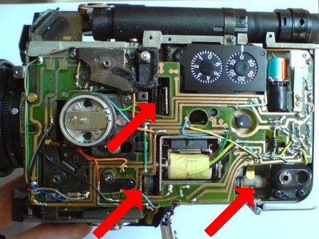
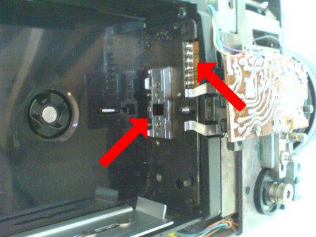
Once the cover is removed the shutter mechanism, top arrow, can be seen. The main motor cog, lower left arrow, can be seen. The shaft and cog that operated the cartridge gear can be seen, right arrow. If the motor does'nt respond to the trigger, the cog (lower left) can be slowly turned towards you using a small screwdriver. Be sure not to touch the circuitry with earthed metal tools, or fingers in case of static discharge. This slow turning, after awhile, may free up a gummed motor. Do not attempt to lubricate any cogs.