Repairing LOMO OKS5-18-1 lens
Note: This page is a direct copy of a page from www.rafcamera.com I have placed it here just in case the original disappears or gets deleted. I considered the page too handy to lose. The original page address is: https://rafcamera.com/info/how-to-tips/repairing-lomo-oks5-18-1-lens
There are numerous website resources regarding camera lens repair and service. Below are just a few examples:
I am not claiming this process as my work, and with all such work I suggest the usual: Seek professional assistance first off, and if you continue D.I.Y then use due caution, correct tools, a thoughtful and cautious approach. All that follows is from the page: WEBSITE
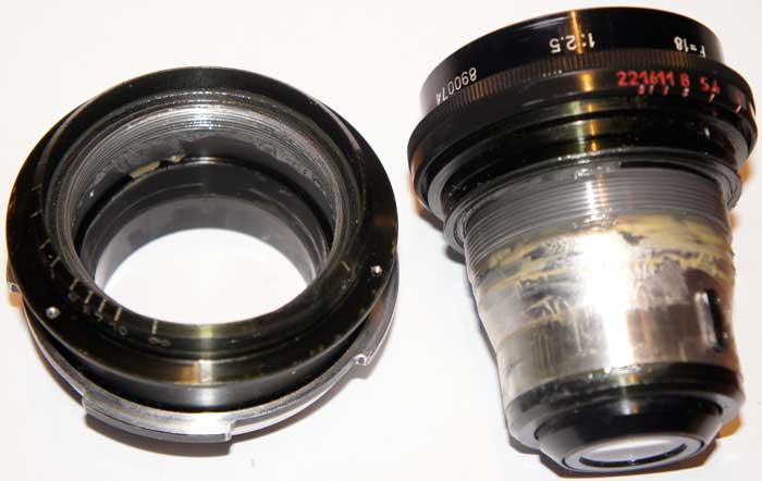
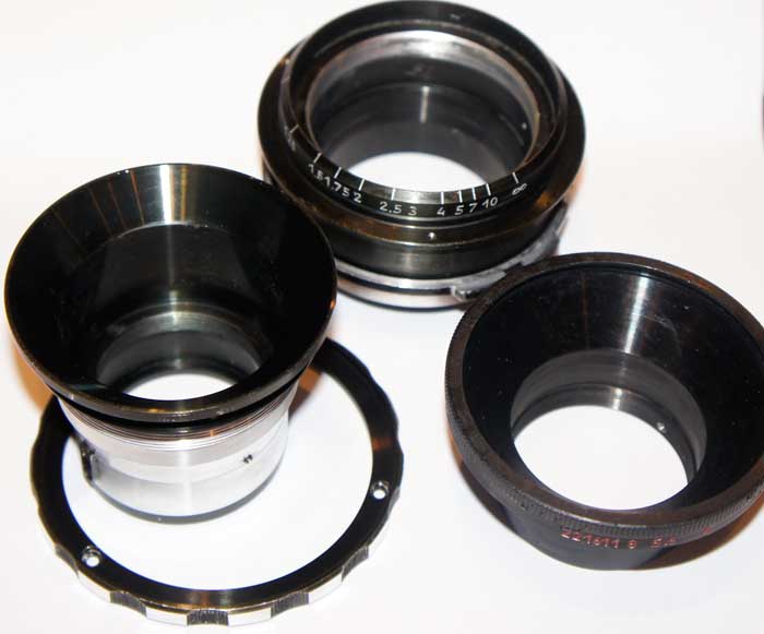
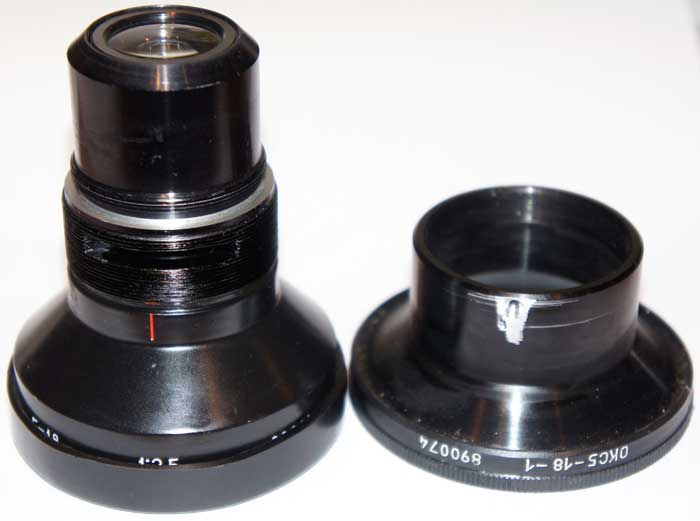
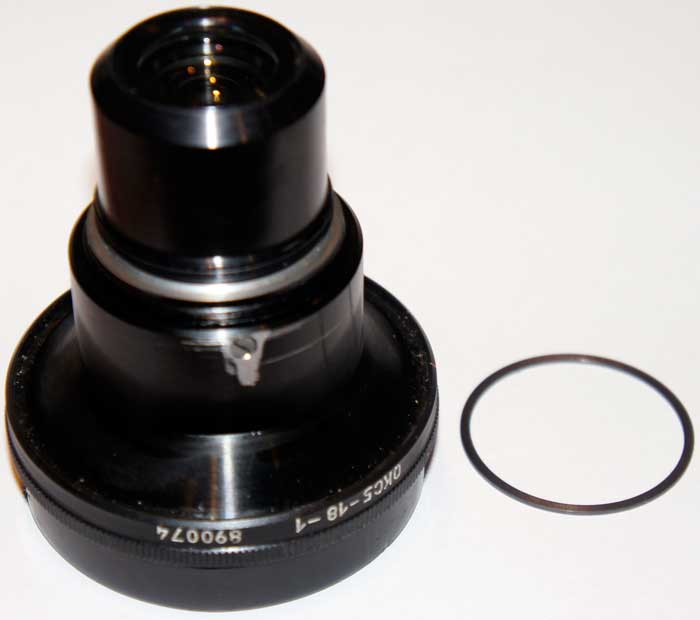
Common problem of this lens is cracks in the inner elements. If you have a spare optical block, you'll be able to repair the lens yourself with just couple of screwdrivers. Here is the broken lens. Its optical block is cracked, and can't be used in professional work.
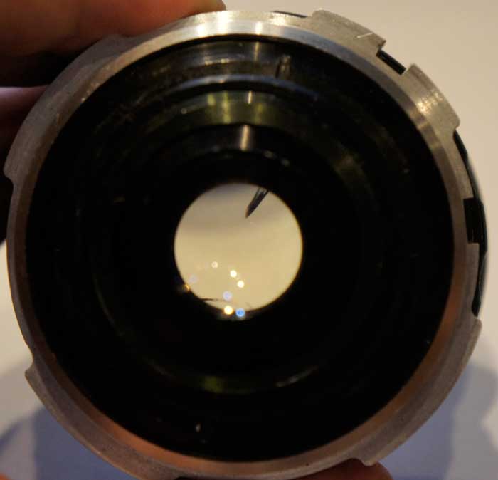
Here is the broken lens. Its optical block is cracked, and can't be used in professional work.
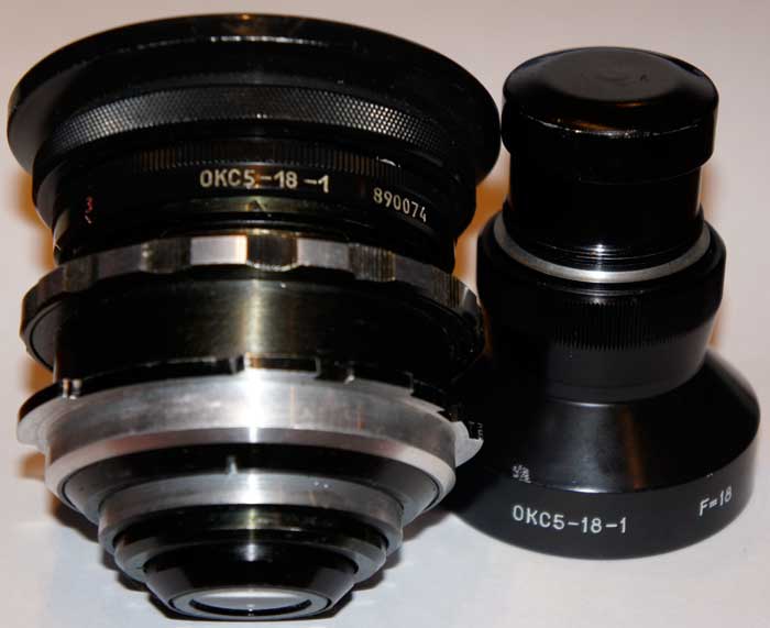
Let's take the spare optical block and proceed.
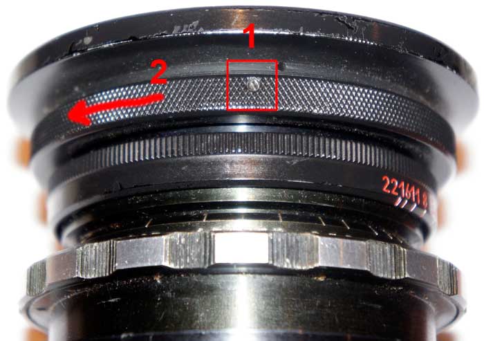
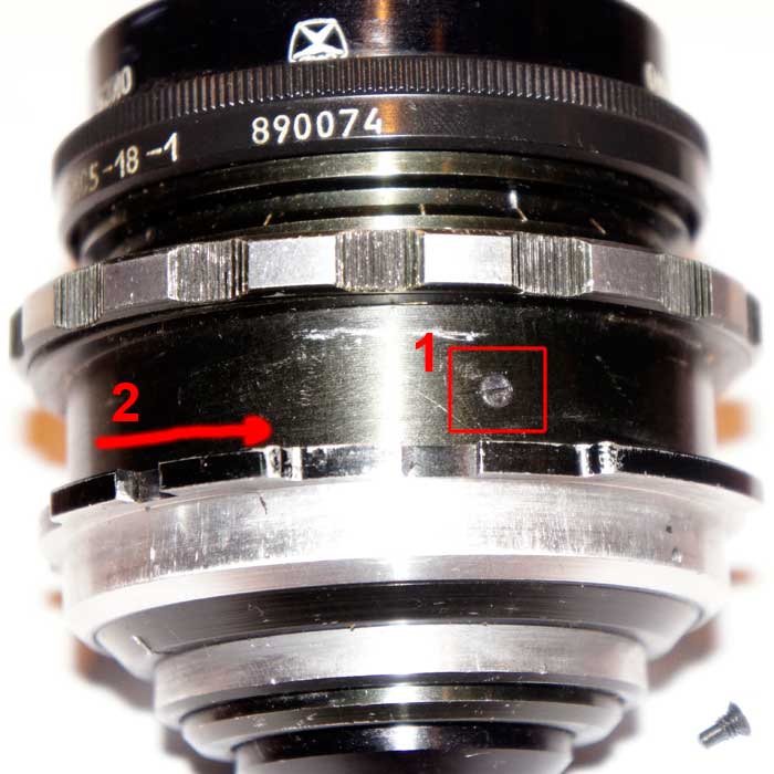
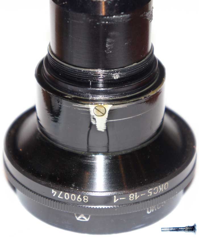
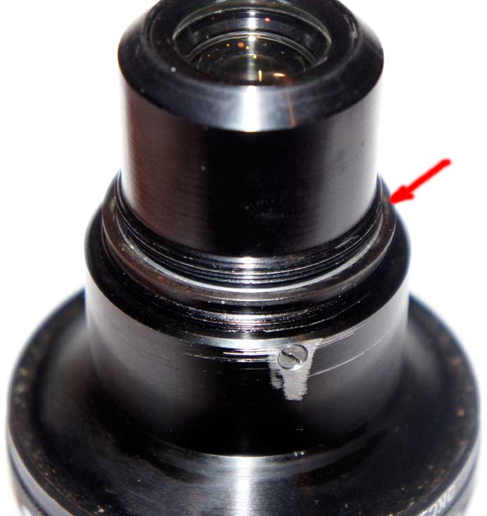
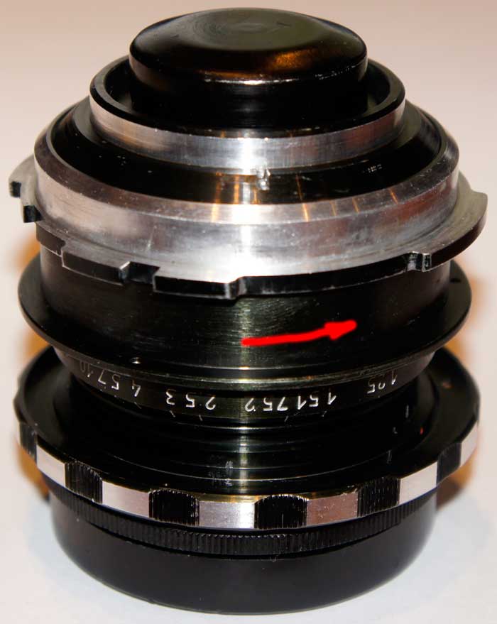
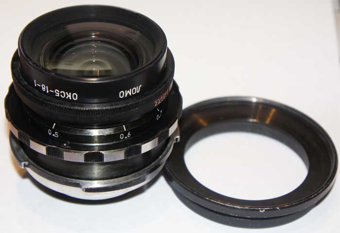
First thing to do is to remove front part with filter thread. To do this, loose the set screw (marked with number 1) and turn the retaining ring in the arrow direction as marked with number 2.
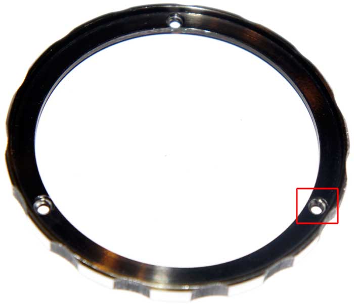
Now, remove three screws holding a focus ring. Actually, this step is not necessary for disassembling, but you may want to clean all parts, and separating the parts will help then.
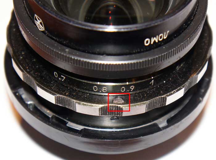
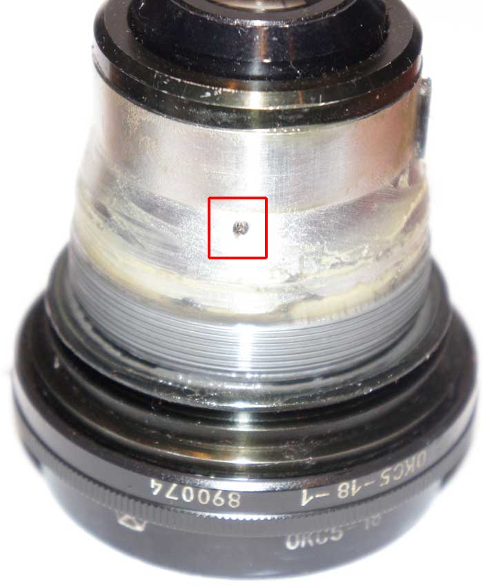
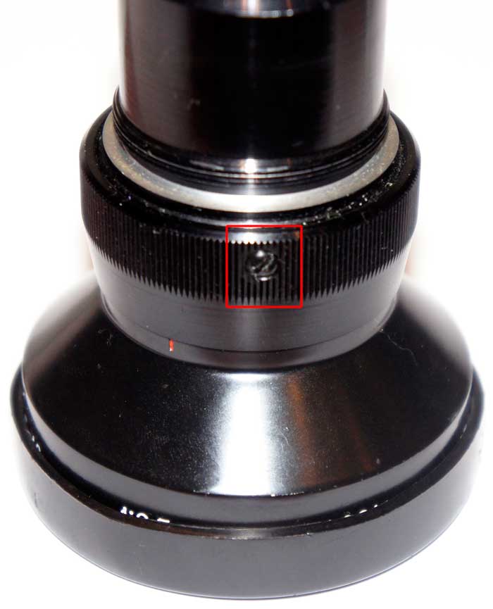
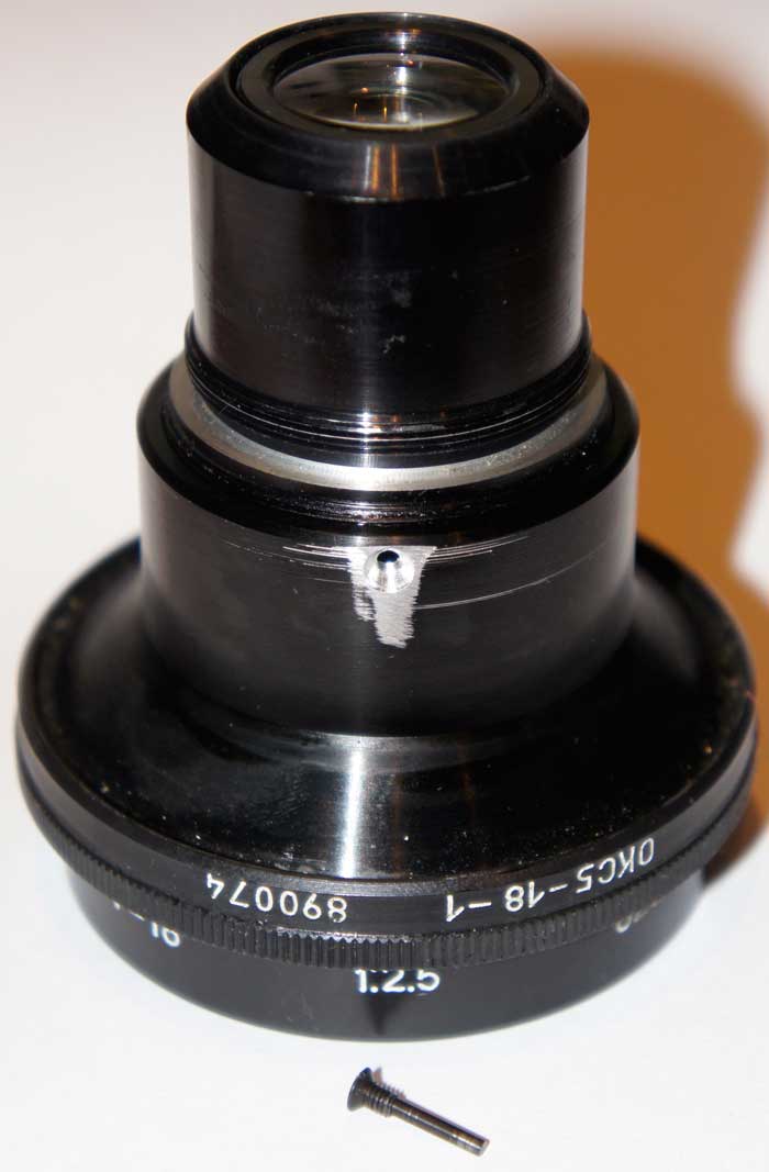
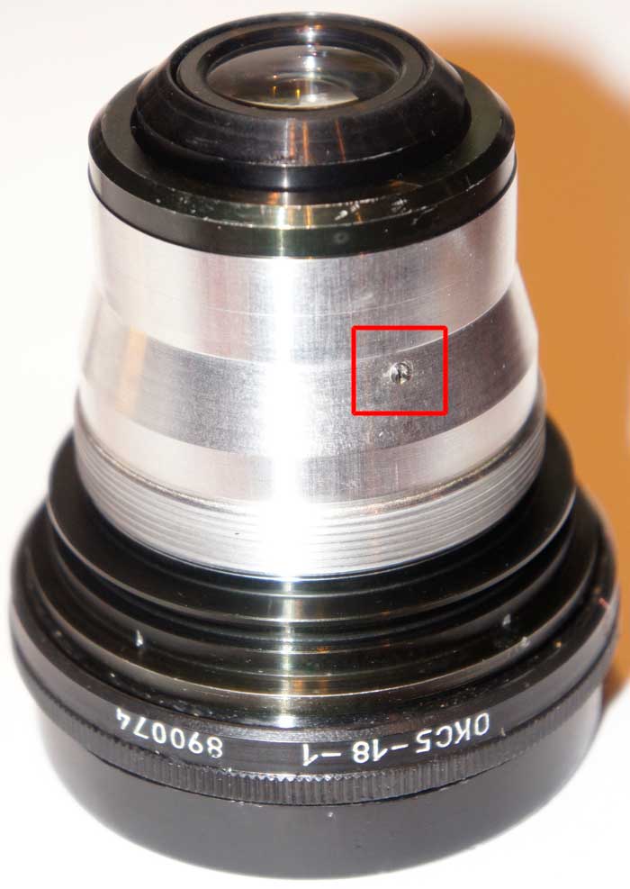
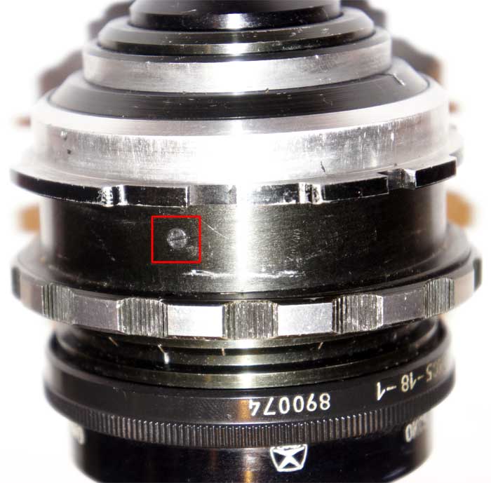
It is time to remove focusing mount now. Remove the screw marked with number 1 below, hold the lens at its front part (where Soviet quality sign is engraved) and rotate the mount in the arrow direction. COUNT TURNS and write down the number . Take note that the screw has stepped form. It serves as a limiter of the focus ring rotation range.
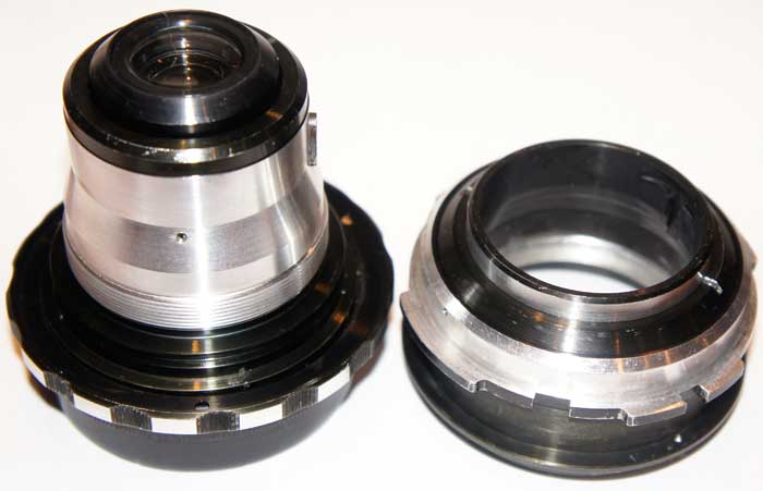
Focusing mount is removed. As you can see, there is quite much of excessive grease. I'll remove it all.
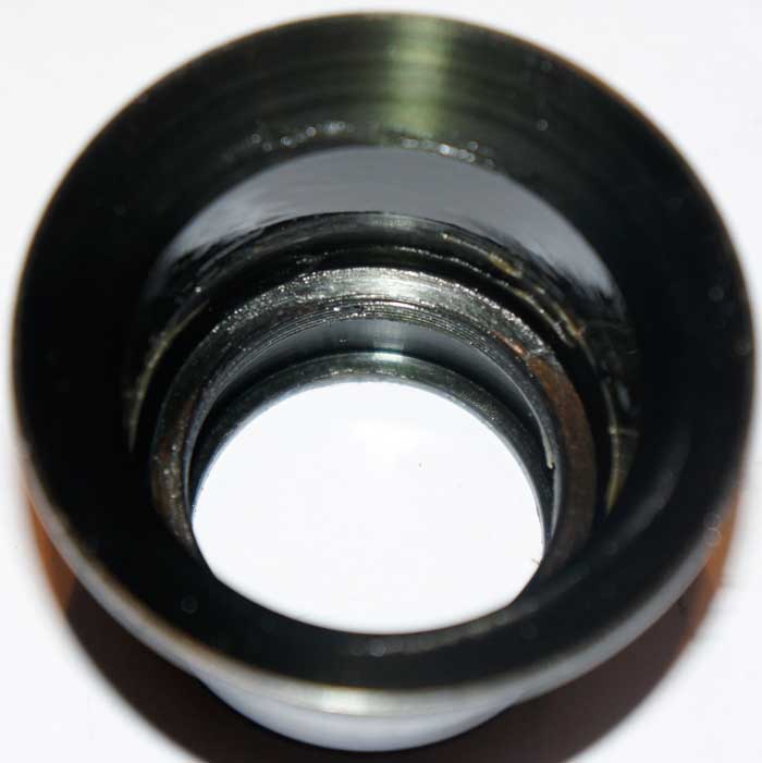
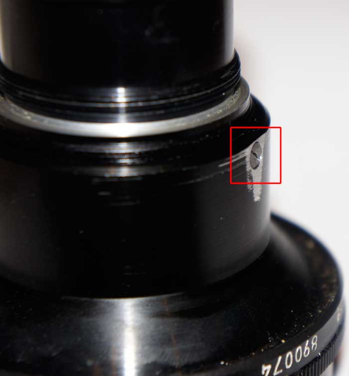
To remove next part of the lens, take off the set screw shown below and rotate the part counter-clockwise.
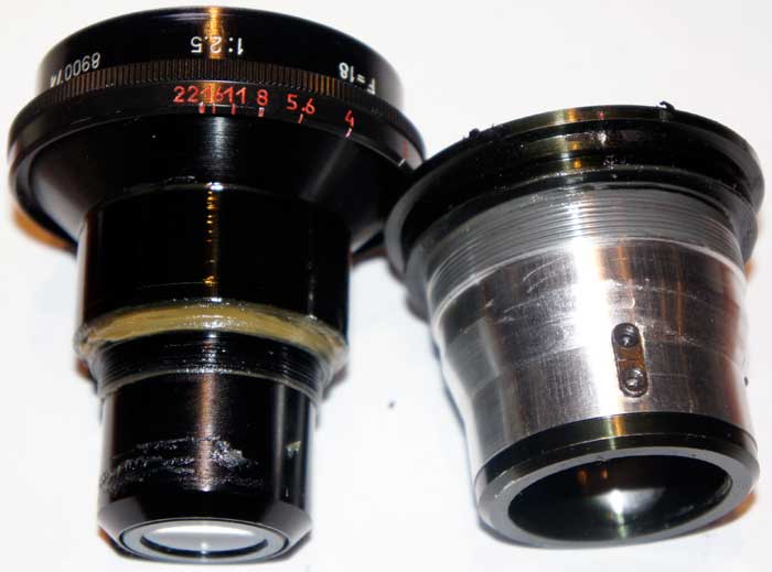
The part is removed, and you can see excessive grease again.
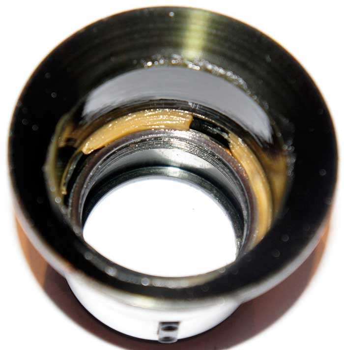
Look inside this part. A spacer should be there. Remove it for cleaning.
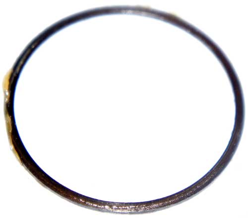
Here is how the spacer looks.
Remove most of grease with cotton sticks.
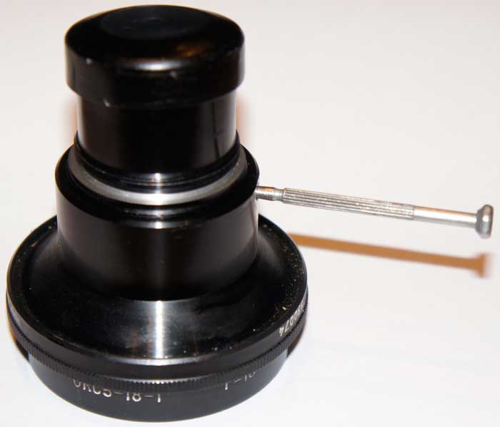
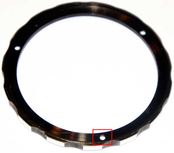
Last part to remove is aperture control ring. Unscrew long guiding screw and rotate the ring counter-clockwise. COUNT TURNS and write down the number .
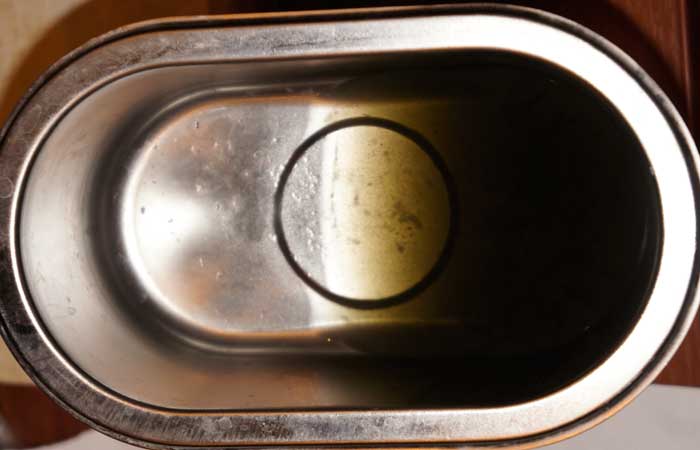
I have an ultrasonic bath used in mobile phone repair workshops. It makes cleaning easier. I'm using dry solvent. Few minutes in such bath makes parts very clean, but excessive grease should be removed with cotton sticks anyway before and after bathing. As you can see on the picture below, there was much dirt in the lens mechanism.
All the parts appear much better after bathing in solvent. I didn't clean the cracked optical block since this seems to be pointless to me. But maybe I'll clean it later and try to sell it for few bucks :-)
Let's prepare the spare optical block now. Main thing to do is to remove the temporary aperture control ring. To do this, unscrew the guiding screw marked below. As you remember, we did the same thing removing the aperture control ring from the original (cracked) block. This means that you have who guiding screws now. In theory, you can use either one during assembling. But in real life gaps of the aperture mechanism may be bit different, so check both screws to see which one fits better.
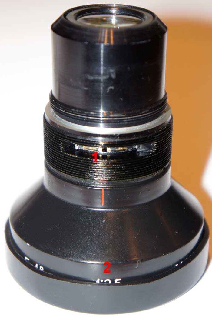
Now, position the gap of the aperture mechanism (1) against red index mark. This will help us to stick the guiding screw into the gap later. Take note that the index mark will be hidden under the aperture control ring, so remember another place that will remain visible. In our case, it is colon in the f-value mark (2). So, we remember that the aperture mechanism gap is positioned against the colon.
Take the aperture control ring.
Place it onto the block and rotate clockwise. Check number of turns you wrote before and make same number of turns. If you are lucky, the slot of the block will be right under the guiding screw hole now. Position the screw hole against the colon mark (or other mark in your case since this position varies).
To make sure that you are in right position, stick a thin screwdriver into the hole and move it to the left and right. Watch through the lens to make sure that diaphragm sizes changes accordingly between limiting positions. If it is so, insert the guiding screw instead of the screwdriver and tight it carefully. Don't apply force, or diaphragm will be deformed and stuck. If you feel effort before the screw sank completely, this may mean that it is not in the mechanism gap. In my case, the ring was removed from the original block in 12 turn, but it took 13 turns on the new block to find correct position. So, some guess and try game here.
Make sure that the guiding screw is down in the countersink completely, or you'll not be able to attach next part.
Next thing to put is the spacer.
Just put it onto its place. No any thread here.
Put the next part on to the block and rotate it clockwise till stop. Make sure that aperture control ring turns smoothly. If it is stuck, turn the last part counter-clockwise a bit. Honestly, I made mistake here - I didn't mark original position of this part. So, don't forget to mark it when you'll disassemble your lens :-) Tight the set screw.
Take note that the focus control ring is bit different from two sides. This side has countersinks for screws. This is front part.
Other side has no countersinks. It is rear part. And this is correct position to put the ring onto the lens. Actually, you may alter the assembling sequence here, and attach the focus ring to the focusing mount first. This may make things even easier. But I just did all the step in reverse order.
The focus ring is put onto the lens, and it is time to screw the focusing mount to the optical block.
Just place it over the block and rotate it counter-clockwise. Count necessary number ow turns.
After you did correct number of turns, put the limiting screw into its place. Make sure that the focusing ring rotates in it's limits between 0.5 and infinity marks against the index mark.
Last thing to do is to attach front filter/cap holder. Put it onto the lens, tight the retaining ring, and tight the set screw.
That is all! Well, not all, actually. Soviets never did items with so strict allowances as it necessary for precise optics and mechanics. So, there is quite high chance that the lens became misadjusted now. Adjusting and collimating will be necessary, most probably. But you've got a lens with non-broken glass now, that is better that you started with :-)
DISCLAIMER:
This is a Copyright Disclaimer under section 107 of the Copyright Act of 1976, allowance is made for “fair use” for purposes such as criticism, comment, news reporting, teaching, scholarship, education and research. Fair use is a use permitted by copyright statute that might otherwise be infringing.
Fair Use permits limited use of copyrighted material without having to first acquire permission from the copyright holder. Fair use is one of the limitations to copyright intended to balance the interests of copyright holders with the public interest in the wider distribution and use of creative works by allowing as a defense to copyright infringement claims certain limited uses that might otherwise be considered infringement.
The creator of this website declares that information and photographs copied from other websites and placed here is solely for the purpose of education and research. The creator of this website does not earn money from information published here. The creator of this website always references, where possible, the original creator of work that is published here.
If any person wants to dispute this, and/or believes the creator of this website has infringed on a person's copyrighted creative material, please email me at mishkin.film@gmail.com
This email address is checked frequently.