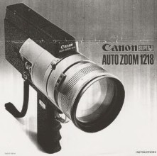
Repair of the Canon 1218 should be undertaken with great care. If a part is broken during disassembly, there are few cameras on the market to use for spares. As with all repair attempts, use correct tools. Below is a user manual for when it works.

|
canon1218_04.zip Size : 4.488 Kb Type : zip |
CANON 1218 LENS REPLACE
FOG: If, when looking at the outer lens, there seems to be fog, chances are it is condensation. This will affect film shot with the camera. The footage will appear either out of focus, or have a softening aura to the footage. Removing the outer lens, cleaning the inside, and reassembling will solve this problem. See caution below.
FUNGUS: When looking at the lens from the front of the camera, and you see what appear to be spider's webbing inside the outer lens, this is fungus. By removing the outer lens, you may be able to either clean it or replace it. Moderately abrasive cleaner may be needed for this. If the fungus is well established, it will have "pock marked" the lens. In this case replace the lens. See caution below.
SCRATCHES OR CHIPS: If the outer lens has either of these problems, replacement is the best remedy.CAUTION!
Lenses have coatings designed to offer the best protection from reflections from outside and inside of the lenses. Coatings also protect the glass from harmful UV rays. If you use an alcohol based cleaner, you run the risk of removing these coatings. Only use a cleaner specific to camera lenses. When dismantling the lens body, be very aware of dust particles and hairs. Use latex gloves when handling lenses.
Although this is picture is off a Canon 814, the same procedure applies. Remove the three small screws on the lens sleeve.
Be sure to mark where on the shroud and body certain markings are made. This help locating the thread of the lens body when re-assembling the lens sleeve.
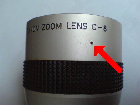
This photo clearly shows the small hole. There will be two opposite each other on the lock ring. Alternate between the two as the ring is unscrewed.
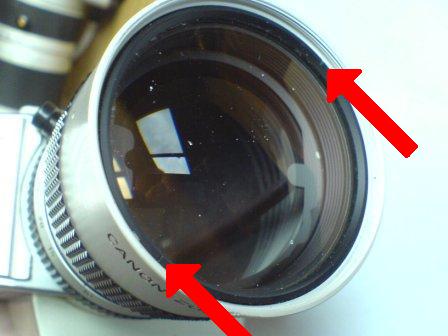
Prior to disassembly, a lock ring must be removed. This holds the lens in place. Use a watch repair tool with a pointed tip to locate the hole and rotate in an anti-clockwise direction. Be careful not to slip and scratch the lens.
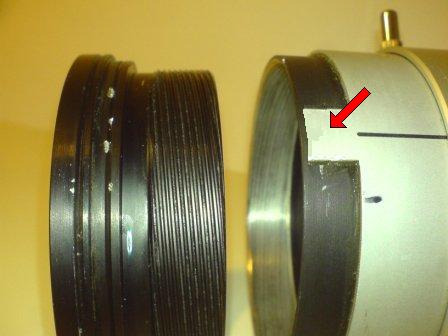
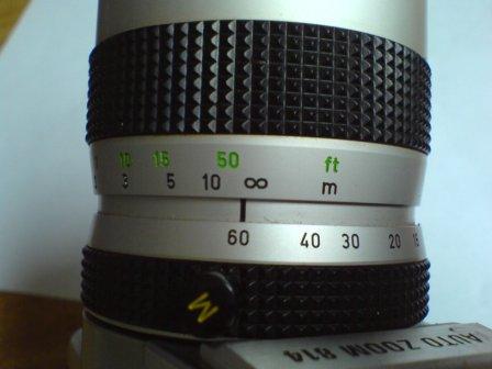
To remove the lens assembly, remove the outer lens sleeve, it has the focus distances printed on it. Once removed, you will see how the lens body rotates, and how the rotation guard stop against the indicated metal tab.
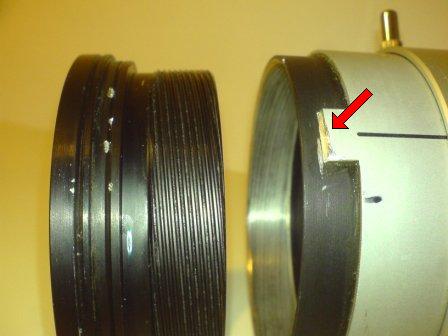
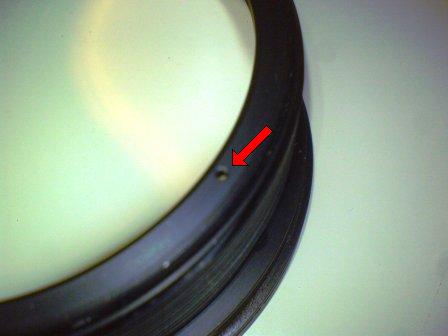
By cutting off the tip of the metal tab you will be able to unscrew the lens housing completely. The downside is that once the camera is re-assembled, you need to ensure a stopper is in place otherwise while focusing you may accidently unscrew the lens.
The thread of the camera lens body and lens housing is aluminium, therefore very soft and easily damaged. Be very careful not to "cross-thread" the lens housing when re-assembling. If the threads' are dirty, clean and apply a small amount of graphite to the thread. Never apply de-greaser or grease.
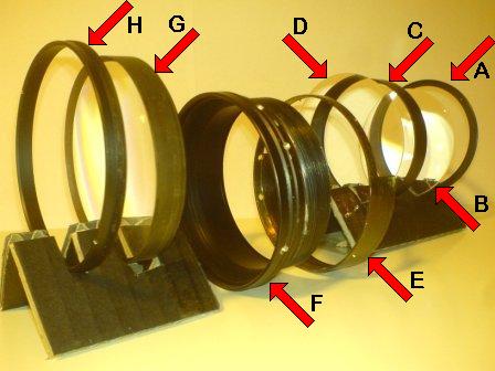
These
are the lenses out of the camera housing. Items "A" through "D", when
assembled fit into lens housing "F". "A" is a lock ring. "B" is a lens
it holds in place. "C" is a spacer that seperates two lenses, a
shallow groove holds lens "B" in place. "D" is a lens that sits on the
opposite side of the spacer to lens "B". "E" is a "cut in" rotation
guard that stops the lens at infinite during focusing. "G" is a lens
that sits into the lens housing. "H" is a lock ring.
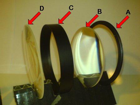
This picture shows in better detail the lens elements of the lens housing. When dealing with lenses, always wear latex gloves, and assemble the "pointed" part of the lens facing away from the camera body.
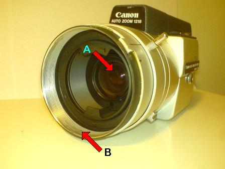
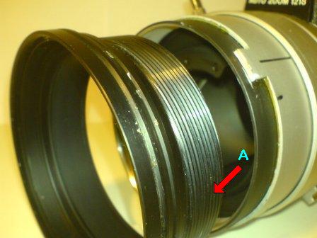
This picture shows the zoom lens and apparatus, "A". This lens is removable via a small lock ring, yet should rarely need replacement. "B" indicates the internal thread of the lens body, be careful not to damage.
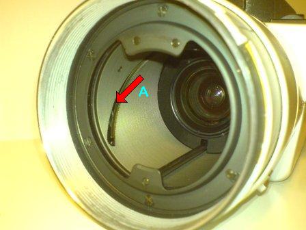
This picture is a closer view of the zoom apparatus, specifically "A", the grooves that enable smooth operation. Be sure that these are clean and contain no particles of dirt.
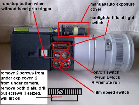
Step 01: Remove the cover on the bottom of the camera,
this will expose the four screws holding the switch cover in place. First remove the round switches, 18fps, 24
fps and the “R” and “L” switch.
Step 02: Each screw switch has two very small screws counter sunk in the side of the switches. If these are seized, or you damage the screw head, drill them out. If you use a smaller drill bit than the screws diameter, you will save damaging the thread, and can use new screws on reassembly. Once these two switches are removed, you can gently pry the cover off.
Step 03: Beneath the cover you will see the switch bases. Each switch base is attached by three screws. Unless you know of a particular switch being faulty, do not remove them. The base plate they are screwed to may gain access to the film advance motor cogs, but removing the base plate nearly damages the camera. Proceed with great caution.
Unscrew the top cover, one screw near the eye piece. Remove batteries and use a small screw driver to remove one screw holding the exposure meter cover in place. Gently push exposure meter cover forward and off. Do not prise off front plastic cover. It breaks
Unscrew the battery compartment cover on the side of the camera, remove batteries. There are four screws, two long screws on the top side of the battery holder. Two short screws on the lower side. Gently lift away, wires are attached. This will expose the film advance motor.
PROBLEM SOLVING
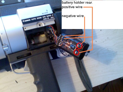
If you insert watch batteries, 1.5 or 1.3 Volt,
and there is no response in the viewfinder, check the battery contacts for
rust. If this does still not work,
examine the rear of the battery holder to ensure the connections are good. If one is broken, lightly solder. If you do solder, be sure to cover your
solder work with tape, in case your connections earth out once placed back into
the camera.
If the exposure and power zoom work, but the
film advance motor does not respond, check all switch surfaces for grime. A build of grime on the contact surfaces
“may” reduce the voltage reaching the motor, or make it intermittent in
function. Also, using a small flat head
screw driver, manually advance the cog connected to the cartridge spindle ANTI-CLOCKWISE. This may take quite a few minutes before
anything happens.
When the motor does
start to operate without manual assistance, be sure to lightly lubricate with
oil of the correct viscosity. Or better
yet, use white grease. Be careful using
a degreaser, as you want the grease to stay on the cogs. Also, liquids may earth connections.
During this stage, use your finger to gauge the temperature of the film advance motor, if it is warm, it is trying. If it is cold, check your connections. If it is hot, give it a break, it is trying to work
If the film counter works, but does not return to zero when the cartridge is removed, the lever arm that disengages the counter cog is sticky. By lubricating lightly and manually moving it back and forth, you can loosen it up.
From within the film cartridge compartment, there are three screws, two on the lower part, and one on the higher part. The cover on the other side of the camera will lift away, be careful as two plastic buttons will fall out. These are the battery test buttons. One white, one red.
Next unscrew the four screws holding the “canon auto zoom” emblem on. This will require gently prising off to expose the power zoom motor.
PROBLEM SOLVING
If you insert watch batteries, 1.5 or 1.3 Volt, and there is no response in the viewfinder, check the battery contacts for rust. If this does still not work, examine the rear of the battery holder to ensure the connections are good. If one is broken, lightly solder. If you do solder, be sure to cover your solder work with tape, in case your connections earth out once placed back into the camera.
If the exposure and power zoom work, but the film advance motor does not respond, check all switch surfaces for grime. A build of grime on the contact surfaces “may” reduce the voltage reaching the motor, or make it intermittent in function. Also, using a small flat head screw driver, manually advance the cog connected to the cartridge spindle ANTI-CLOCKWISE. This may take quite a few minutes before anything happens.
When the motor does start to operate without manual assistance, be sure to lightly lubricate with oil of the correct viscosity. Or better yet, use white grease. Be careful using a degreaser, as you want the grease to stay on the cogs. Also, liquids may earth connections.
During this stage, use your finger to gauge the temperature of the film advance motor, if it is warm, it is trying. If it is cold, check your connections. If it is hot, give it a break, it is trying to work
If the film counter works, but does not return to zero when the cartridge is removed, the lever arm that disengages the counter cog is sticky. By lubricating lightly and manually moving it back and forth, you can loosen it up.