WEBSITE UPDATE:
Due to the increased difficulty in people accessing this website and the sister, due to certificate issues from Yola, I am slowly migrating to Wordpress during 2023. These camera repair pages will remain here, but will no longer be updated.
For recent cine resource updates, please visit: https://aussiecine.wordpress.com/
For recent camera listings, please visit: https://aussiecinerepair.wordpress.com/
Downloadable User Manual
KIEV 16U (windup)
The only difference between the 16UE (electric) and the 16U (windup) is the detachable motor. A spring wound motor can be attached to the electric version, but an electric motor cannot be attached to the windup version. The windup version has frame rates of 12, 16, 24, 32, 48 and single frame. These cameras were considered semi-professional and as well as amateurs, were used for television and by small studios. (reference page)
Company Information: Kiev Automation Plant named after G.I. Petrovsky (on some movie cameras the manufacturer was designated as “Tochpribor factory”) from the second half of the 1950s to the 1980s, he produced 16-mm film cameras, which were used mainly for professional purposes. Filming apparatus “Kiev-16U”, designed for filming films on various topics and in a variety of conditions. Designed to work with 16 mm film with one-sided or two-sided perforation wound on a reel. The reel capacity is 30m or 100ft of film. The camera is equipped with three lenses on a rotary turret: Vega-7 (2/20 mm), Mir-11 (2 / 12.5 mm) and Tair-41 (2/50 mm) The lens mount is M32x0.5 (reference page)
Lubrication: Prospective D.I.Y lubrication should be researched well, as some cameras have very specific requirements, requiring specific oil and/or grease. For most of the camera maintenance i have done i use “Singer machine” oil for gears and cogs, a light viscosity oil suited for low load and speed applications, commonly used for sewing machines. I use aerosol Inox-3 to treat metal surfaces and Inox-6 synthetic grease on sliding parts.
Note: As with all equipment such as old cameras, a qualified service person is ideally the first stop when owning a camera. If, however, a person is moderately confident and not heavy handed, basic maintenance will assist in keeping the camera running long enough for you to enjoy using it and then save up money to get it serviced.
CAUTION! When working on a spring winding camera always ensure the spring is run down entirely. Not only is it potentially dangerous to work on anything with a coiled spring inside, the camera motor accidental running a few hundred frames could mess up your marking needed for reassembly.
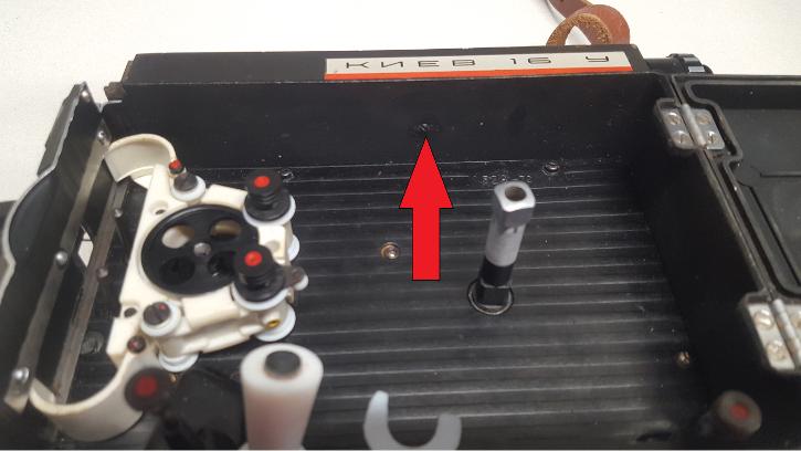
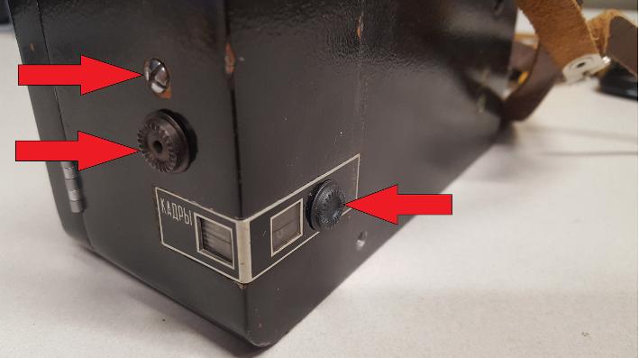
REMOVING SPRING MOTOR
To access the spring motor remove the winding arm by unscrewing the indicated screw anti-clockwise. The small screw also needs to come out. Once removed the metal cover will lift off.
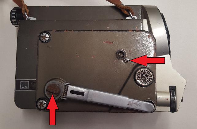
Once the cover is removed the spring can be seen. Loosening the two indicated screws will allow the spring motor to be manoeuvred off the camera body. If the spring coil is broken, very unlikely, do not attempt to open the spring coil casing. Dismantling spring coils is very dangerous and may cause injury. The spring motor will not need further dismantling unless a part is broken or misaligned.
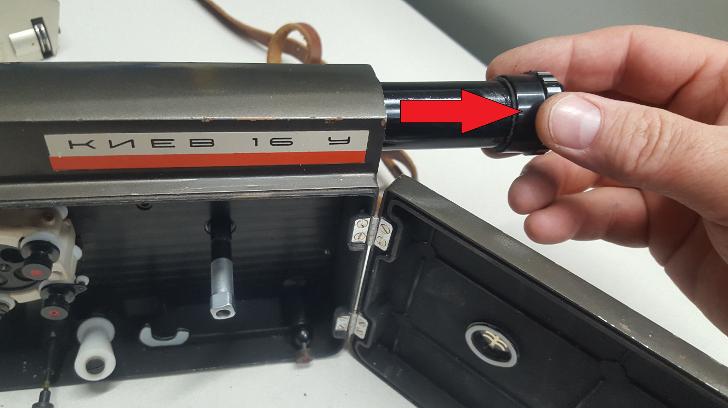
This picture shows the slotted pin and groove it fits into. Once the screws are loosened, the spring motor can be wiggled free by sliding it in a 45 degree angle towards the front of the camera.
The spring motor assembly should be sonic cleaned and re-greased or oiled. There is a small copper coloured governor that assisted with controlling the spring motor speed. Do not lubricate this. With the cogs, apply one or two drops of sewing machine oil.
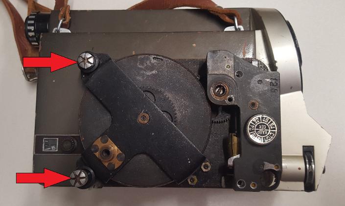
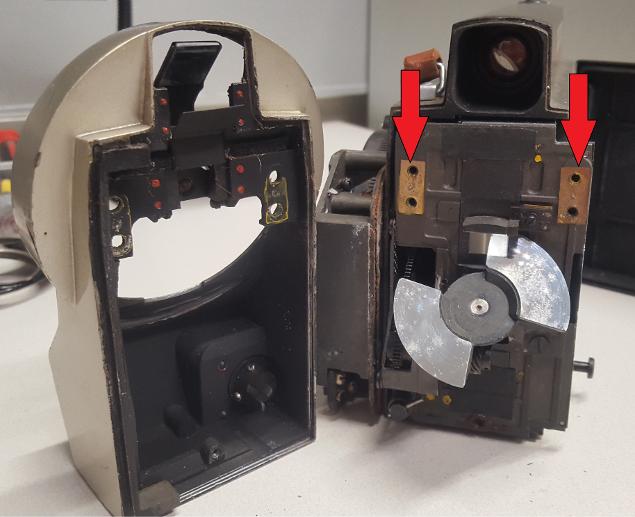
On later models there are two screws in a different position to earlier models, as well as the spring handle remaining in the same spot.
Once the cover is removed, there are are two screws holding the spring motor to the camera body. Only remove the two indicated, other screws are securing the spring motor covers and should not be removed incase the spring unwinds in a dangerous manner.
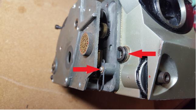
The spring motor is still held by a pin, as per earlier pictures. The two items indicated do not secure the motor to the body. The small spring clip retains the winding handle once it is stowed into the cover. The arrow on the left indicated a securing part for an electric motor.
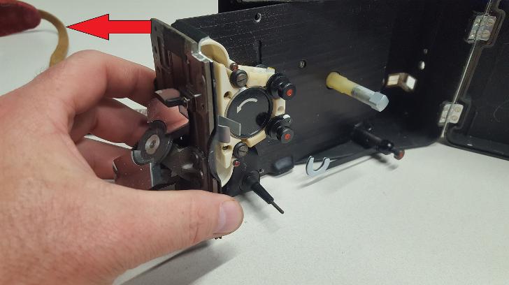
REMOVING LENS TURRET
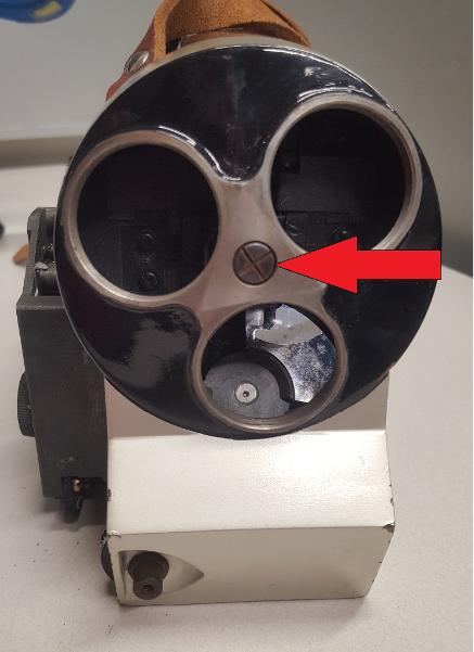
Undo the screw in the centre and pull the turret free from the camera.
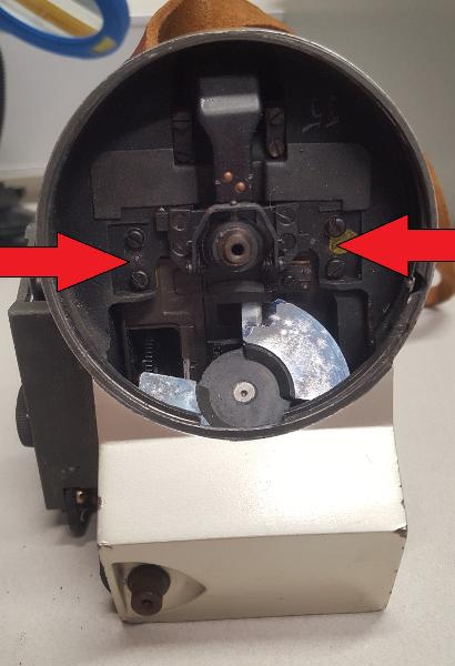
Once the turret is removed, undo the four screws as per the arrows.
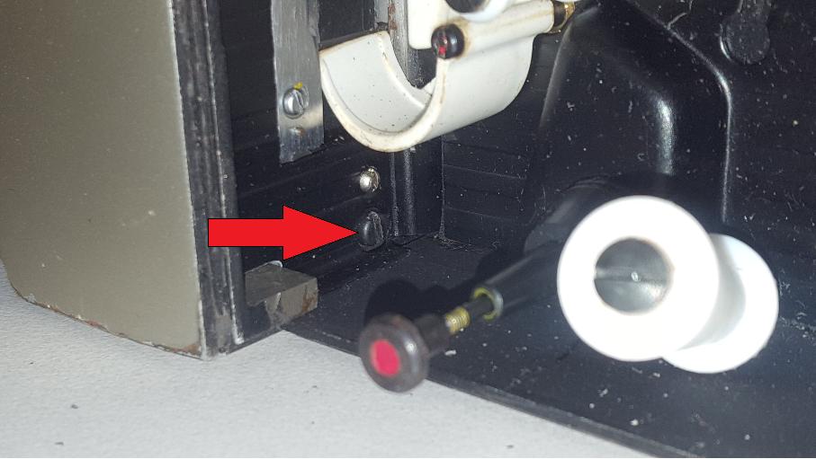
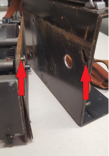
From within the film chamber, undo the indicated screw.
Now the turret can be pulled away from the camera. Two arrows indicate a shim each side. Shims are commonly used to ensure either a proper fit between two surfaces, or as is common with cameras, to ensure the lenses are situated at exactly the correct distance from the film plane.
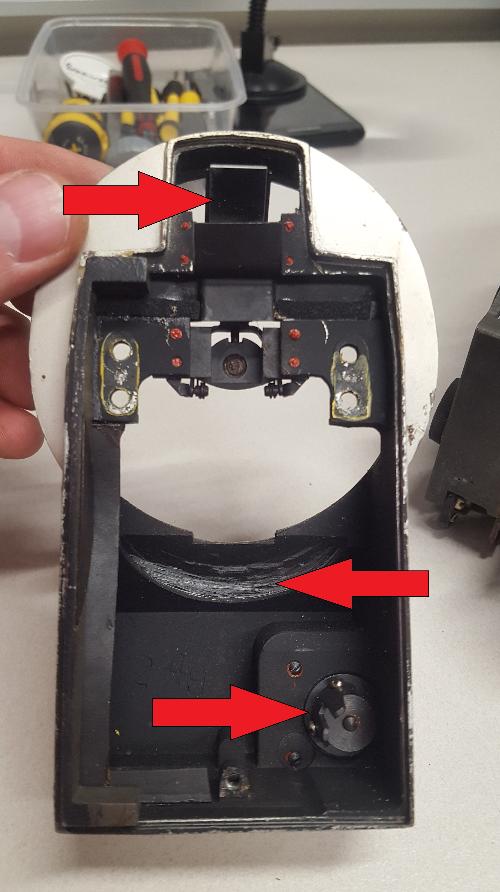
The top arrow indicates the 45 degree mirror that conveys light via the ground glass to the viewfinder. The mirror will need cleaning. The middle arrow indicates an area that has had its paint scratched away manually. This was likely done in the factory to prevent the shutter from hitting the turret. In some factories during the soviet era, machining tolerances are poorly calibrated, requiring tolerances to be manually adjusted during assembly, ie removing coatings from castings, or adding shims. The bottom arrow indicates the rear of the dial that switches the camera between "RUN", "SINGLE FRAME", and "OFF" Spraying a touch of lubricant here will make the dial easy to turn.
This picture shows the ground glass and how it is secured. The ground glass is secured with glue to the small metal elbow. If removing, be sure to mark it's exact position. Also, there are likely shims in place to ensure exact measurements.
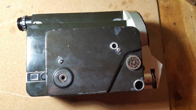
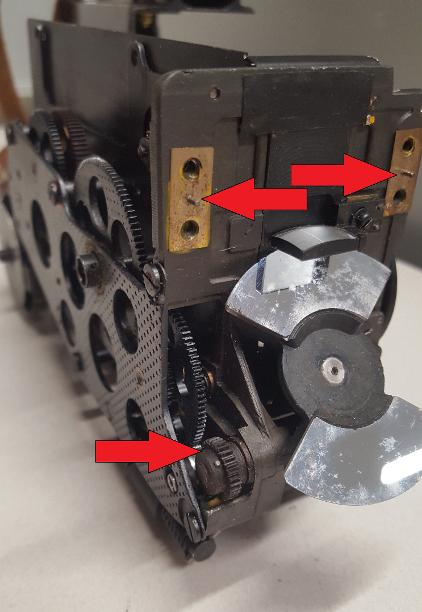
REMOVING GEARED INTERNALS
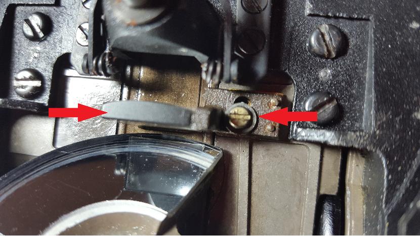
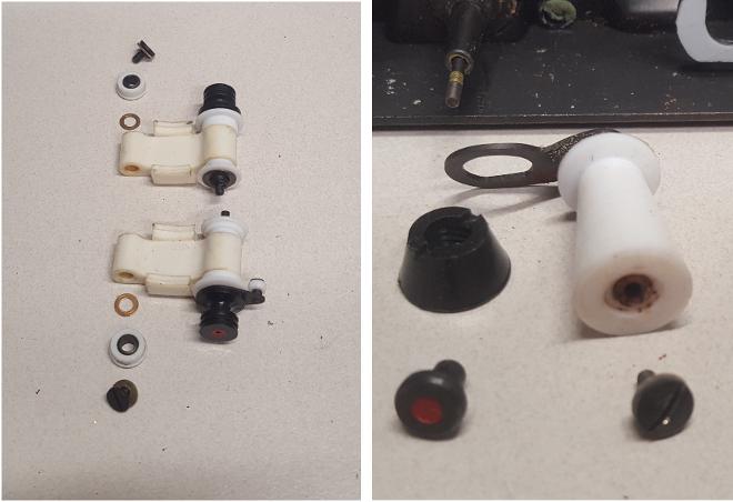
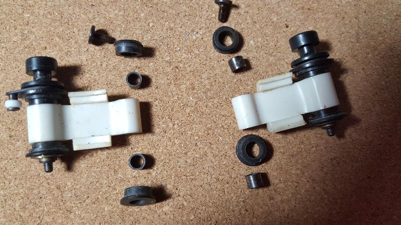
To start, remove the angled roller assembly. Unscrew the red dotted nut, as per the arrow, and unscrew the large plastic nut below it. Now the assembly will lift off. The two horizontal arrows indicate the film locks, these may be removed at this stage for cleaning.
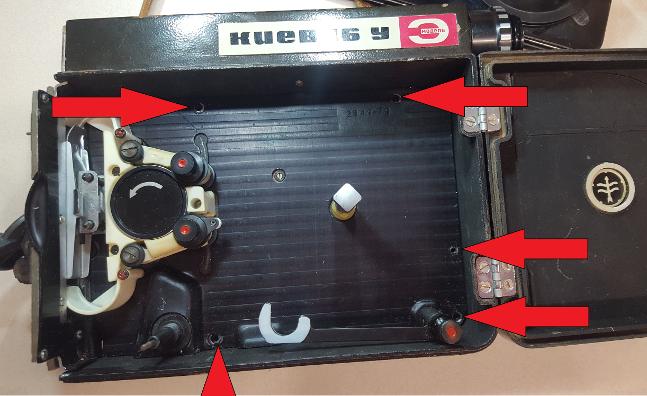
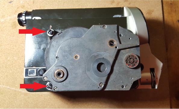
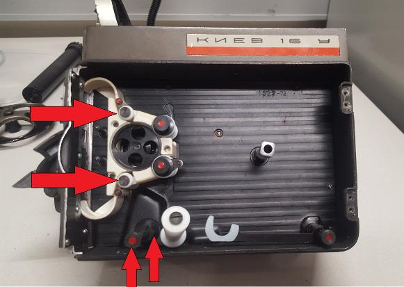
Undo the five indicated screws.
Remove the screw, and use a small screw driver to pry off the two dials. They are a friction fit and will lift off without being damaged.
The clockwork assembly will now slide forwards and at an angle to the camera body.
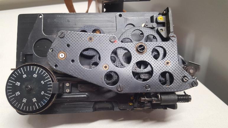
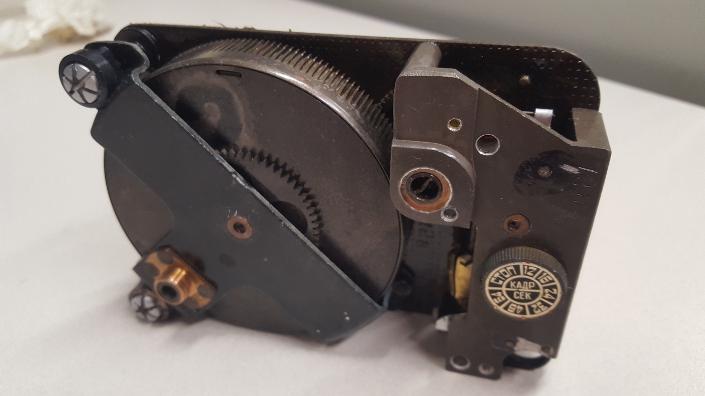
Once removed, the gears and dials can be easily recognised and examined. This assembly can be submerged in a cleaning solution within a sonic cleaner. Before doing so, be sure there are no felt or material parts, or electrical switches such as one on the 16UE electric model. The dial assembly to the left is easily removed. See below explanation. The cleaning solution I used was 30% household surface cleaner, 20% window cleaner and 50% warm water. Once the assembly is removed from liquid after cleaning, some metal surfaces will need protecting from flash rust straight away. Wiping such exposed metal surfaces with spray lubricant like CRC, WD40, or Inox-3 will prevent flash rust occurring.
Be sure to note which shim belongs on which side, just in case they are different thicknesses. Close examination of the cogs indicates lots of dust build up.
Always take pictures of the order with which items are assembled. These will be placed into a sonic cleaner.
It should be noted that over the time the 16U and UE were produced, there were likely many variations between model years, such as the different components used on the left and right, and the design of teh spring motors.
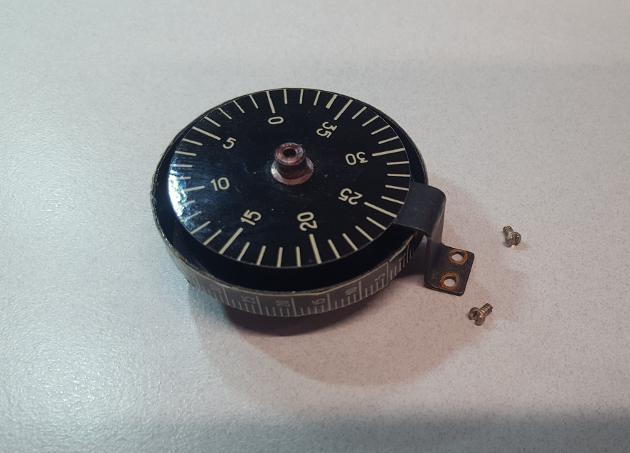
Remove this dial assembly from the clockwork assembly before submersing the body in liquid in a sonic cleaner. The top dial is painted, however the paint may lift while being cleaned. The dial underneath is paper glued to a disc.
REMOVING VIEWFINDER