WEBSITE UPDATE:
Due to the increased difficulty in people accessing this website and the sister, due to certificate issues from Yola, I am slowly migrating to Wordpress during 2023. These camera repair pages will remain here, but will no longer be updated.
For recent cine resource updates, please visit: https://aussiecine.wordpress.com/
For recent camera listings, please visit: https://aussiecinerepair.wordpress.com/
Auricon 16mm cine cameras:
The Auricon cameras were developed in 1940's America. At the time many cameras were being developed and increasingly used by the public, various industries, and news services. Auricon cameras were unique in the way they recorded sound while filming. The Auricon's recorded sound onto the film directly, so filming on location was considerably easier and the sound was high quality. Auricon's were designed to be used with a recording amplifier, Auricon's came with various types of recording amplifiers and later external recorders. Auricon's are considered one of the best cameras available from the hey day of camera manufacturing from the 50's to the 80's. Their quiet running and quality ensure that even in the 2000's cine film makers consider the Auricon a valuable and sought after 16mm camera. Ironically, Cinema Products cameras eclipsed Auricon in the 80's due to Cinema Products developing their cameras toward users' needs. However, due to the CP16 circuitry board's tendency to corrode, effectively disabling the camera, the Auricon has eclipsed the CP16 as it has no circuit board. So, when the last CP16 becomes inoperable, the Auricon cameras will still be working.
Auricon Optical Sound group: https://groups.io/g/AuriconOpticalSound
A web site devoted to all things Auricon, very active, helpful members, a wealth of knowledge regarding using Auricon cameras in the modern age.
Wikipedia Page: https://en.wikipedia.org/wiki/Auricon
A wealth of information on the Auricon cameras and history of the factory.
Milton David Holmes Auricon site: https://sites.google.com/site/mdavidholmes/auricon-16mm-cameras
A must visit to learn about the Auricon cameras and history.
Lubrication: Prospective D.I.Y lubrication should be researched well, as some cameras have very specific requirements, requiring specific oil and/or grease. For most of the camera maintenance i have done I use “Singer machine” oil, a very light viscosity oil suited for low load and speed applications, commonly used for sewing machines.
Note: As with all equipment such as old cameras, a qualified service person is ideally the first stop when owning a camera. If, however, a person is moderately confident and not heavy handed, basic maintenance will assist in keeping the camera running long enough for you to enjoy using it and then save up money to get it serviced.
Disclaimer: The information here is not intended to be a comprehensive assessment of the Auricon cameras. It is intended as a basic guide on a "chop top" Prospective camera tinkerers should always proceed with caution when attempting their own repairs, read as much as you can, search manuals and online information, and ask questions.
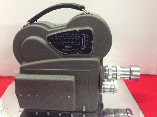
Auricon CM72 -standard model
The Auricon CM72 was a very popular camera, very dependable, quiet, and well made. In it's standard form it was 100ft internal load. Due to the increasingly popular use of 16mm cameras for news gathering, many people wanted greater film stock loads, 400ft was increasingly the considered standard when filming news events or interviews. As mentioned above, the Auricon cameras were able to record sound on film, dependably and with good results for broadcast news. For this reason the camera remained the recognised standard of which other 16mm cameras were compared. However, Auricon did not produce a CM72 with a 400ft magazine option.
Image courtesy of: https://www.worthpoint.com/worthopedia/auricon-cinevoice-model-cm-72-16mm-1719805221
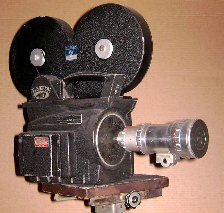
Auricon CM72 "chop top" -modified
The Auricon CM72 below is a good example of the types of modifications offered by numerous companies to answer the demands of many Auricon camera users. Compare the picture of the standard Auricon CM72, and you will note the top was "chopped off" and a plate was placed on top to make use of 400ft magazines such as the Mitchell magazine. The motor was replaced also. Companies offered different modifications, so each Auricon may be largely or slightly differetn from others. They were highly modified due to their dependability, quality, and silent running. The camera being disassembled on this page is a "chop top" that has also been modified for use with PAL.
Image courtesy of: http://d.web.umkc.edu/dmskb8/products.asp
Manuals

|
Auricon Cinevoice 16-mm Motion-picture Camera manual.pdf Size : 1172.718 Kb Type : pdf |
|
|
Auricon Super-1200 16-mm Motion-picture Camera manual.pdf Size : 926.808 Kb Type : pdf |
|
|
How to use your Cinevoice.pdf Size : 5002.877 Kb Type : pdf |
|
|
MC-571 frezolini.pdf Size : 1084.558 Kb Type : pdf |
Note: There are many Auricon manuals across the internet, the above are just a sampling. Above listed sites have manuals available.
POWERING UP THE AURICON CM72-A
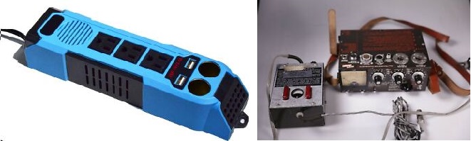
Power accessories for the Auricon CM72
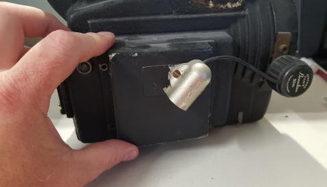
The Auricon needs 120 Volts, low amperage to run. There are original power leads designed to run these cameras. There are also battery packs and amps designed to power the camera when 'in the field' These items are still occasionally available, but most require repair or adjustment as they are quite old now. There are a variety of D.I.Y methods to power up Auricon's, from batteries wired in serial, to 12volt to 120volt converters such as the one pictured below.
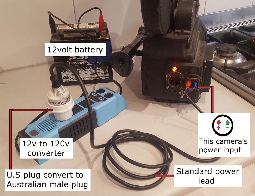
Running the Auricon CM72
This Auricon is hooked up to a 12volt motorcycle battery. The picture is fairly self-explanatory. The camera above has a different power plug in the back of the camera body compared to many cameras. Remember, these cameras were the most modified 16mm camera's due to their widespread use and quality. To find out a specific camera's power connections, look inside the camera body, red will always be the 'live' wire.
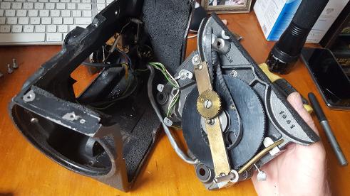
DISASSEMBLING THE AURICON CM72-A
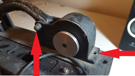
Remove the film magazine, then loosen the leather handle and push out of the way. Then remove both screws securing the cover.
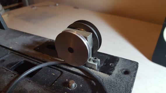
Removing the cover exposes the clutch and the belt from within the camera is visible. Before removing the clutch which is secured with two screws, mark with a sharp scribe or fine pen the clutch's exact position where it mounts to the camera body as this will assist during re-assembly.
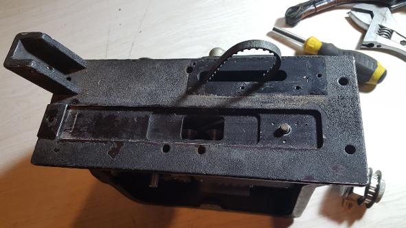
Once the clutch is removed, remove the remaining 6 screws and lift the top plate away.
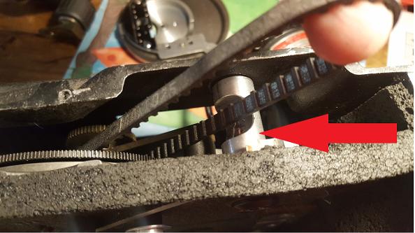
Be aware that the cylinder the top large screw secures from inside the film chamber, has a groove in it to allow the belt passage without rubbing against it. During re-assembly be sure to check this cylinder is turned in a way as to not rub against the belt.
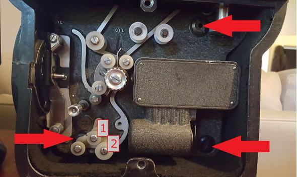
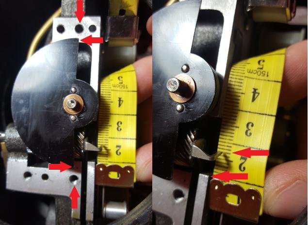
Next remove screws 1 and 2 to expose a large screw underneath, then the lower right screw, and then loosen top one. It will not come out, as it is secured by a screw on the opposite side of the camera... see below photo.
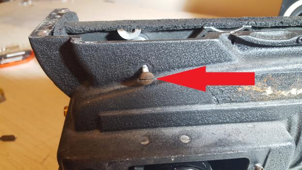
The top large screw will not get removed easily, loosen the above screw, then the inside cylinder can be removed.
Next, the front lens turret/mount needs to be removed. Remove the four screws.
Around the turret is a rubber sound proofing O ring. This can be gently prised out. Use a sharp pointed instrument to get started, then use fingers to remove. The rubber used is high quality and should not break. Old paint will likely flake off.
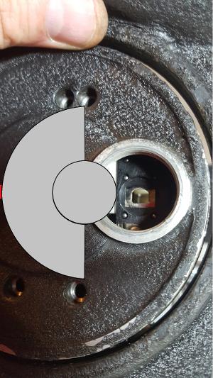
Now that the turret plate is ready to be removed, the shutter has to be rotated into a position that will allow the turret plate to be removed without catching the shutter. Slowely rotate the camera motor until the shutter is in the above position.
The turret plate can be gently pushed from the inside of the camera by placing pressure on the above indicated solid parts. Do not use a screw driver or tool, gently pressure with fingers only.
As the turret plate becomes loose, gently remove it being sure not to catch the edges of the shutter. if you feel resistance, gently wiggle the turret plate, again, being sure not to catch the edge of the shutter. If you catch the edge of the shutter, you will lift the shutter off its spindle and lose track of it's correct position.
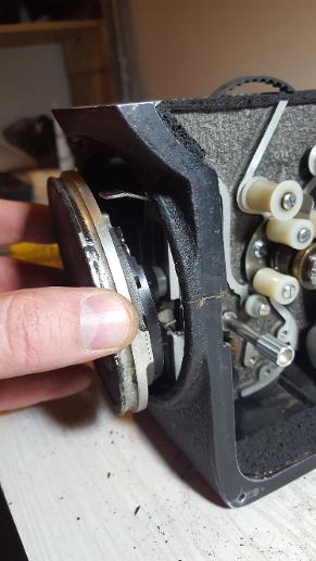
With the turret plate removed, one can see the shutter sitting on its shaft. The turret plate has a cavity that the shutter shaft rests in. Re-configuring the shutter into the correct position can be a very arduous task. See below picture for further info.
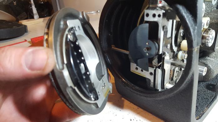
During disassembly of the turret plate, the shutter may left off its spindle and cog, and become out of calibration with the pull-down claw. While this occurring is not the worst thing to happen, correcting it can take many attempts and can only be proved calibrated once film is run through the camera to test your work. However, by using the above method, the shutter and pull-down claw can be calibrated. First, move the pull-down claw into position by rotating manually the film advance cog in the film chamber, place it 7mm away from the indicated edge of the housing.
Now, gently place the shutter onto it's spindle, so that when falls into place and slots in with the shutter drive cog, the edges of the shutter line up with the screw holes as per picture. If the shutter does not line up, gently lift it off, turn in a few mm either clockwise or anti-clockwise, and try again.
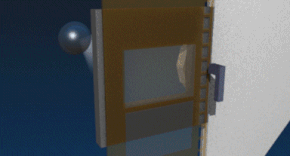
Below is an animated GIF that portrays the shutter and pull-down claw principle. Almost every cine camera employs the same design, if the adjustment is out, resulting film image will be smeared. GIF animation cutesy of: https://en.wikipedia.org/wiki/Rotary_disc_shutter

|
Moviecam_schematic_animation.gif Size : 288.02 Kb Type : gif |
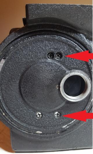
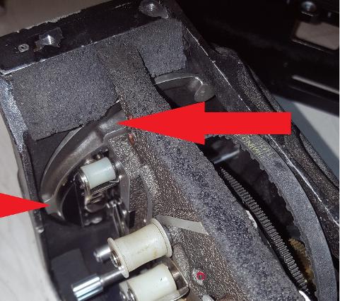
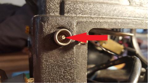
Time to remove the motor via the side plate. Four screws are easily removed.
The motor is attached with three screws. Use a magnetic tip screw driver to assist in preventing screws falling into the camera body if you need to remove them.
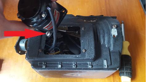
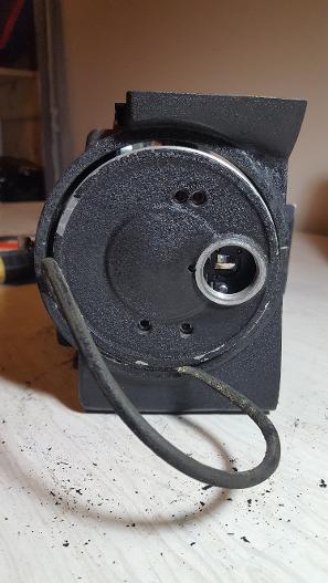
Lifting the motor out of the camera body is straight forward. If you do not have a magnetic screwdriver head, leave the screws in the holes as the motor is pulled clear of the camera body. This will assist when placing the motor back in. The position of the motor is not important, the position of the lead is, placing the motor back in the same position ensures the power lead will not bind if too tight, or get caught in a cog if too loose.
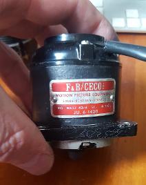
From the name plate on the motor, this camera was modified by F&B camera equipment company. A large company based in New York and LosAngeles, and was one of many companies that modified Auricon cameras.
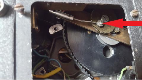
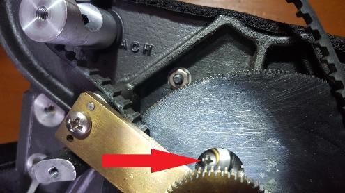
Once the motor is removed you can access the footage counter arm that runs off the main cog. There is no nut on the other side of the indicated screw, the screw threads into the cog.
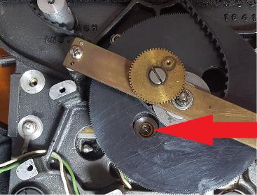
Next, use a fine blade screwdriver to remove th eindicated screw. The knurled knob will pull free.
Remove both screws and the footage counter will fall free from the camera body.
This footage counter fails to properly work. Most likely one of the tiny palls are failing to engage the number cogs. Past experience dealing with counters puts me off dismantling this one as often counters are delicately put together, and most fall into numerous pieces and take hours to reassemble.
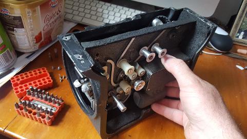
Once all the above items have been removed the camera mechanism is ready to be removed from the camera body. Holding the galvanometer, gently lift the rear and pull to the side.
While lifting slowly, double check for items that had not being disconnected or catching on other parts.
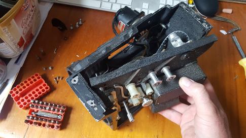
Once the mechanism is free it can be cleared from the camera body. The mechanism can now be easily examined, cleaned, re-lubricated, and replaced if need be.
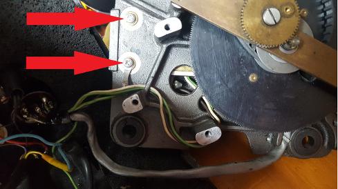
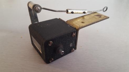
The galvanometer is secured with four screws, two of which are easily accessed, as indicated. Take special notice of the wire that is attached to the body. This is an important earth connection. Unless necessary, do not remove the Galvanometer. It has been secured in accurately and it's correct position is essential for recording sound properly.
Once the two screws are removed, rotate the main cog until a third screw is exposed. Remove this.
Keep rotating the main cog until the fourth screw is exposed. Remove.
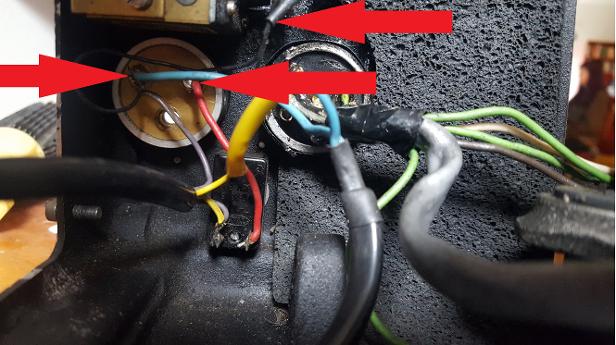
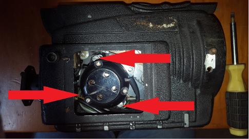
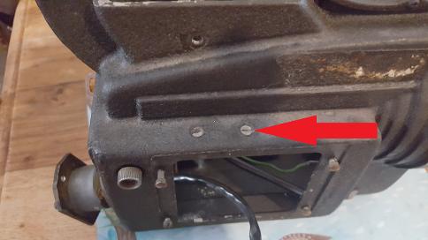
From the inside of the camera body the electric switches are easily accessed. The plug on the left is the power input plug, live and earth wires are indicated. The plug on the right is the audio amplifier plug.
DISCLAIMER:
This is a Copyright Disclaimer under section 107 of the Copyright Act of 1976, allowance is made for “fair use” for purposes such as criticism, comment, news reporting, teaching, scholarship, education and research. Fair use is a use permitted by copyright statute that might otherwise be infringing.
Fair Use permits limited use of copyrighted material without having to first acquire permission from the copyright holder. Fair use is one of the limitations to copyright intended to balance the interests of copyright holders with the public interest in the wider distribution and use of creative works by allowing as a defense to copyright infringement claims certain limited uses that might otherwise be considered infringement.
The creator of this website declares that information and photographs copied from other websites and placed here is solely for the purpose of education and research. The creator of this website does not earn money from information published here. The creator of this website always references, where possible, the original creator of work that is published here.
If any person wants to dispute this, and/or believes the creator of this website has infringed on a person's copyrighted creative material, please email me at mishkin.film@gmail.com
This email address is checked frequently.